Figured out how to do the spinning cylinder effect. Use a motor! Specifically, this motor below.
 |
| A Vex 2-wire Motor 393 |
Unfortunately, to add it to the prop, it means disassembling the prop.
 |
| Oh well... |

Then the motor was mounted by cutting a space into the cardboard section of the handle to fit it and hot glueing it.

Below is the circuit I will be putting on Myrtenaster.

I bought these RGB LEDs

Soldered all 20 in parallel with each other.
 |
| Ugh never again... |
Close up on the array. Added hot glue to solidify the array.

Stuffed it into the blade and tested it. Got red, blue, green, and cyan. All of the red combinations, besides red itself, didn't work.


Upon closer inspection of the circuit, red doesn't turn on because it requires lower voltage to turn on, taking all of the juice and not letting the blue or green lines to light up. Options now are to buy a pot (potentiometer) or apply a regulator to each line after the switch.
As I waited for the new parts to ship, I got to attaching the blade to the prop. Like so.

I also soldered the wires to the 1-pole 12 position switch to get it ready to mount to the prop.

Mounted it to the prop with a fitted pvc fitting and hotglue.

Also finished up putting the rest of the fins in.

I got a pot (potentiometer) in my parts package. Something like this guy below.
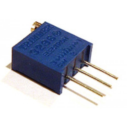
Shown below is the new schematic with the pot.

The above schematic was put on a breadboard and mounted on the prop. The pot was then adjusted with a screwdriver while attached to the red line. Indeed it was a voltage problem, at the right adjustment, purple and all other colors came up as expected.
The connections were then attached to the 12 position switch and tested. What ended up happening was that the powered lines of the switch ended up traveling through the other nodes of the circuit, resulting in the blue position coming up as cyan if a cyan connection was made. Voltage needed to be stopped at certain nodes in order for the all of the colors to show up properly.
To solve this problem, rectifier diodes were used. Something shown below.

Circuit schematic with the diodes.


Here are all of the colors activated through the 12 position switch. Photos where taken with a fan ceiling light as background lighting.
 |
| Blue |
 |
| White |
 | ||
| Red |
 |
| Purple/Violet |
 |
| Yellow. It's much more yellow in real life. |
 |
| Green. It's actually greener than this in real life. |
 |
| Cyan |
Phew!
Things left to do:
-create handle(handle not complete)
-prettify
part4
No comments:
Post a Comment